Workshop Exercise 1.5 - Investigating the Example Workload
Table of Contents
- Objective
- Step 1 - Introduction to the Workload
- Step 2 - The MQTT Broker
- Step 3 - The Simulator
- Step 4 - The Controller
- Step 5 - The WebUI
- Step 6 - The Assembled Application
Objective
In this exercise, we are going to investigate the workload we’ll be deploying to the edge device in various deployment configurations: installed directly into the Operating System, in containers managed with podman, and then on top of MicroShift.
This exercise will cover:
- The components of the application and their functions
- The required communication between the components
Step 1 - Introduction to the Workload
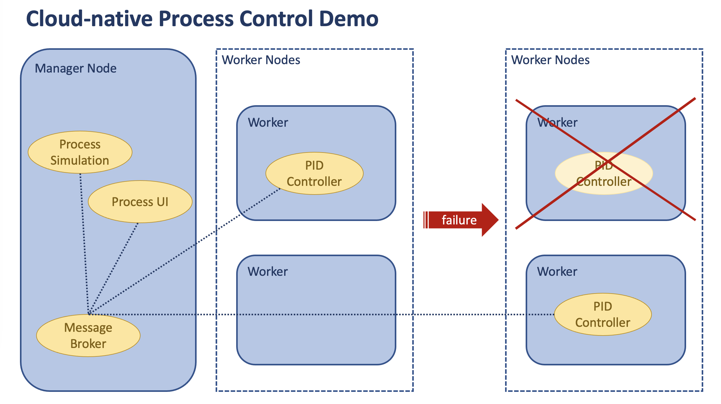
For our workshop, we’ll be running a brew kettle simulator comprised of four components:
- A lightweight MQTT broker - we’ll be using Eclipse Mosquitto
- A simulator for the tank, heater, and temperature sensor
- A controller that relays information between the simulator and the WebUI
- A WebUI that can control temperature and graphs information
A big thank you to Rockwell Automation’s Advanced Technologies group for allowing us to leverage this application.
Step 2 - The MQTT Broker
We’ll be using a lightweight MQTT broker to pass messages between the other components of the application.
For ease of use, we’ll be setting the broker to listen on port 1883 and allow anonymous publishing of messages:
listener 1883
allow_anonymous true
In a production setting these would not be acceptable, as anyone on the network could publish messages to the broker. However, throughout the lab, we’ll leverage a few different methods to control access to the broker, such as firewalld rules, running it inside of a pod with no mapping to host ports, etc.
Step 3 - The Simulator
This brew process simulation includes a tank with a temperature sensor and heater. It is responsible for the following:
- The simulation communicates via MQTT topics with the controller and visualization components.
- The simulation, MQTT broker, control and visualization components are independent services.

This component will need to communicate with other parts of the application, but does not need to be accessed directly.
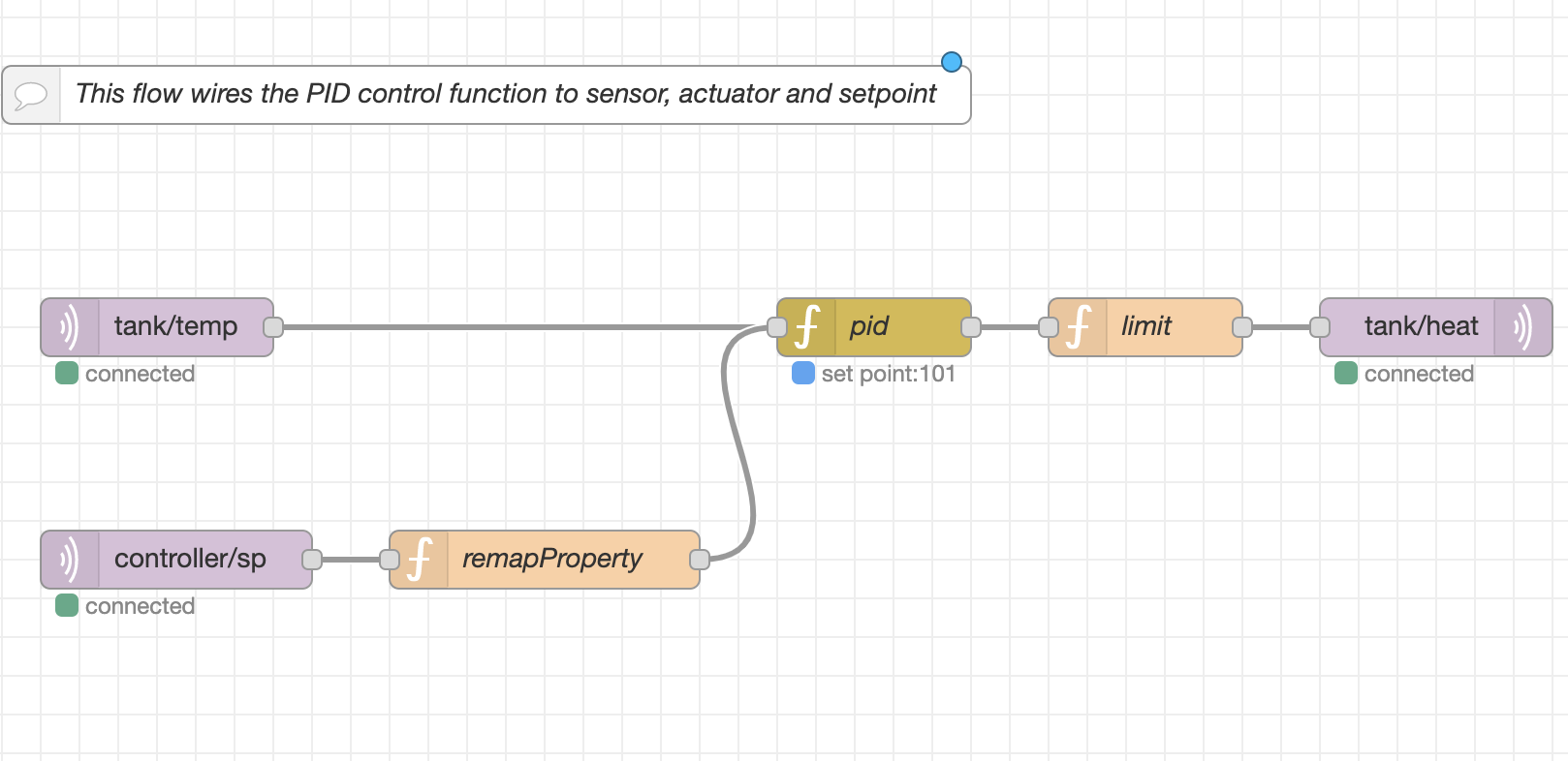
Step 4 - The Controller
This component takes input from the WebUI as well as information from the simulator and determines how much energy should be added or optionally, should the heater even be on.
This control function is wired up as such:
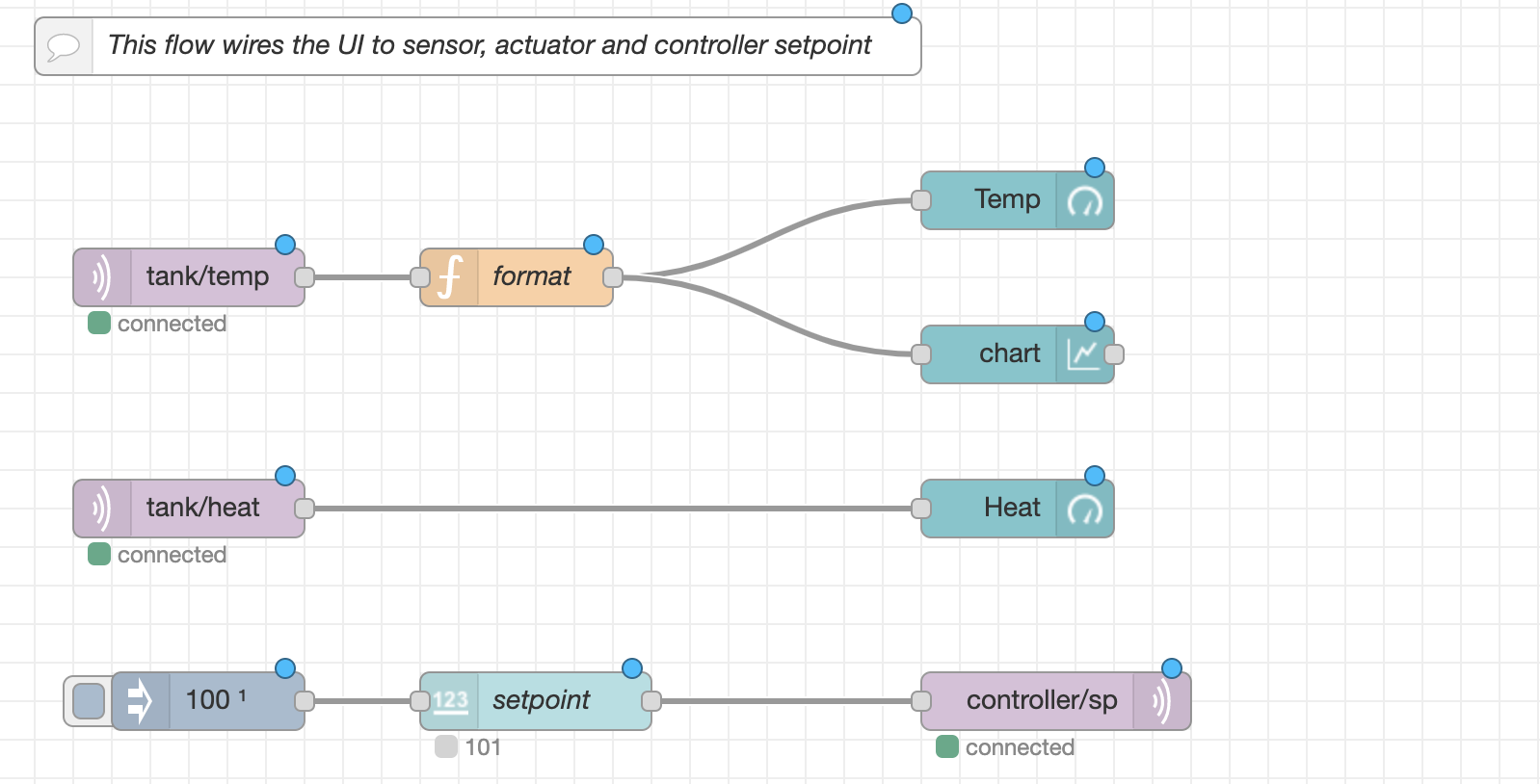
Step 5 - The WebUI
Finally, this component provides a web interface, allowing for the interaction with the simulated system. The wiring is as such:
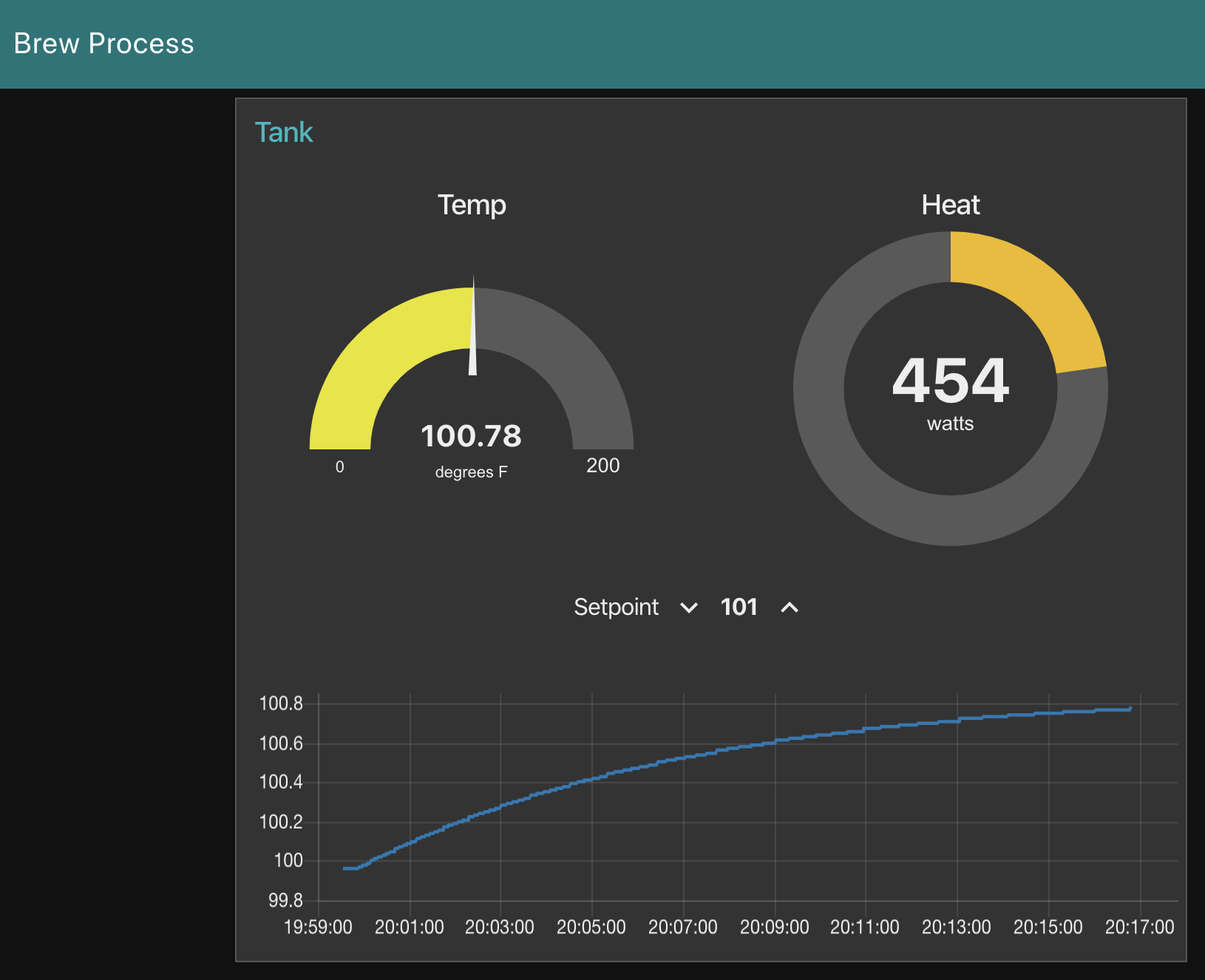
Step 6 - The Assembled Application
Should all components of the application be functioning and communicating, visiting the web interface should present an interface where the setpoint of the tank can be adjusted up or down, and a few metrics will be displated as the controller attempts to bring the system to the sedired set point:
Navigation
| Previous Excercise | Next Exercise |